


Physical Property Testing of Metals
We have outlined our general procedure for determining the density of impermeable metals. This structured approach ensures reliable and consistent data for material characterization and quality control purposes in accordance with ISO 3369 standard.
While we have provided a summary of our process here, it is essential to refer to the full standard for detailed guidance on preparing test specimens, conducting tests, and interpreting the results.
Specimen Preparation
The specified volume of all specimens was larger than 0.5 cm3 and were typically cylindrical and were prepared using precision machining, ensuring smooth surfaces free from foreign material, dirt, grease or oil.
Specimen testing and conditioning were conducted at room temperature, defined as 23°C ± 5°C (73.4°F ± 9°F), and relative humidity of 50% ± 10%, ensuring stable environmental conditions during measurements.
Apparatus
For mass measurements a precision balance was utilized and specimens were suspended on a upper or lower rack. The weighing liquid was distilled water in all cases held in a large beaker.
Procedure
- The test piece was placed on the upper rack and the lower rack was suspended and immersed into the vessel containing the distilled liquid water, all air bubbles we're removed and then mass measurements taken.
- The test piece was then placed on the lower rack and was also immersed into the vessel containing the distilled liquid water, all air bubbles we're removed and then mass measurements taken.
Test Outcomes
As per the equation laid out in ISO 3369 the density of the metal was determined.
For the listed material properties in the Manta Materials data tables, the values are averaged from multiple test specimens per standard, with adjustments made for testing tolerances and uncertainties.
Tensile Testing of Metals at Room Temperature
We have outlined our general procedure for tensile testing metallic materials at room temperature, this structured approach ensures reliable and consistent data for material characterization and quality control purposes in accordance with ISO 6892-1 and ASTM E8/E8M standards.
While we have provided a summary of our process here, there is no substitue to reading the full standards which provide detailed guidance on preparing test specimens, conducting tensile tests, and calculating the desired mechanical properties.
While both standards aim to determine similar properties, they differ in aspects such as specimen dimensions, gauge lengths, and testing speeds. Both approaches have been taken when producing our materials database.
Specimen Preparation
All test specimens were machined, ensuring that the material was free from cold work, notches, machining defects or overheating.
- ISO 6892-1: Unless otherwise stated, flat, rectangular type 1 section tensile specimen types were used for all tests, with the dimensions as detailed below.
- ASTM E8/E8M: Unless otherwise stated, sheet-type tensile specimen types were used for all tests, with the dimensions as detailed below.
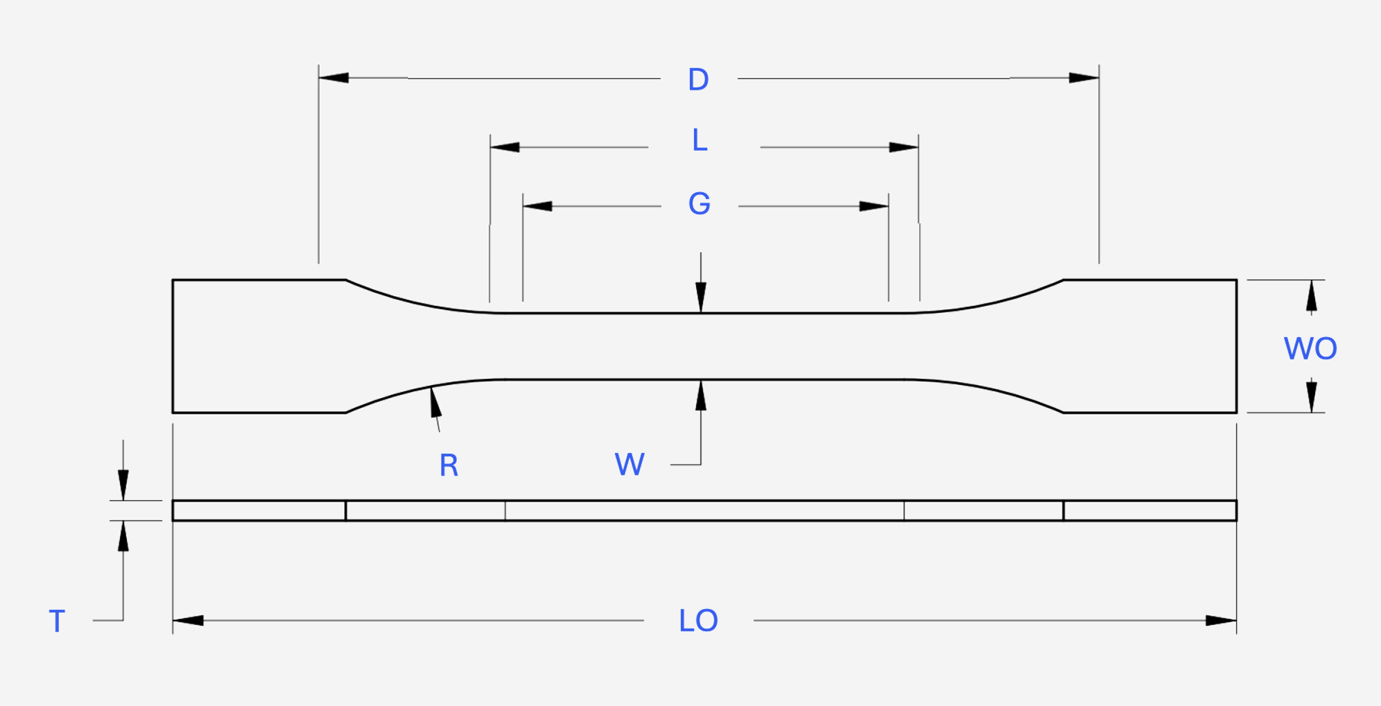
| # | Dimensions | ISO 6892-1 Type 1 | ASTM E8/E8M Sheet Type (Metric) |
|---|---|---|---|
| W | Width of narrow section | 12.5 | 12.5 |
| L | Length of Narrow Section | 57 - 75 | 57 |
| WO | Width overall (minimum) | > 15 | 20 |
| LO | Length overall (minimum) | 137.5 | 200 |
| R | Radius | > 20 | 12.5 ± 0.1 |
| G | Gauge Length | 50 | 50 ± 0.1 |
| D | Distance between grips | 87.5 | 150 |
| T | Thickness | Varies | Varies |
Specimen testing and conditioning were conducted at room temperature, defined as 23°C ± 5°C (73°F ± 9°F).
Apparatus
All testing was conducted on a universal testing machine fitted with a contact extensometers, these systems were calibrated in accordance with ISO 7500-1 and ASTM E4, for the force-measuring system as well as ISO 9513 and ASTM E4 for the extensometer.
In the majority of test cases, wedge grips were used for sample holding, with the full face of the wedge in contact with the specimen.
Procedure
By default five specimens of each standard are tested with the following test procedure steps:
- Specimen Measurement & Marking: The specimen dimensions across the reduced section were measured using calibrated micrometers and the gauge section length was marked.
- Specimen Mounting: The specimen was mounted in the grips, ensuring no misalignment and the machine was zeroed.
- Applying Load: The default test mode was applying force based on strain rate control in order to minimuze variation in test rates between samples. Controlled tensile force was sustained until fracture.
- Data Collection: Record the load-extension or stress-strain data throughout the test.
Test Outcomes
The following mechanical properties are calculated from the tensile test data:
- Yield Strength: The stress at which a material begins to deform plastically, this property us defined differently in each standard.
- Tensile Strength: The maximum stress the specimen can withstand before breaking.
- Elongation: Measured as the increase in gauge length after fracture, expressed as a percentage of the original gauge length.
- Reduction of Area: The decrease in cross-sectional area after fracture, expressed as a percentage of the original area.
For the listed material properties in the Manta Materials data tables, the upper and lower bounds are calculated from the test specimens from both standards as well as an additional margin to account for test tolerances and uncertainty.
Flexural Testing of Metals at Room Temperature
We have outlined our general procedure for flexural testing of metallic materials at room temperature. This structured approach ensures reliable and consistent data for material characterization and quality control purposes in accordance with ISO 7438 and ASTM E290 standards.
While we have provided a summary of our process here, it is essential to refer to the full standards for detailed guidance on preparing test specimens, conducting flexural tests, and interpreting the results.
Both standards aim to determine similar properties but differ in aspects such as specimen dimensions, span lengths, and testing configurations. Our materials database incorporates both approaches to provide comprehensive data representation.
Specimen Preparation
All test specimens were prepared using precise machining techniques to ensure flat, smooth surfaces and edges that are free from notches or other defects that could affect test results.
- ISO 7438: Specifies the use of rectangular or cylindrical specimens. The length, width, and thickness of the specimens must be within specified tolerances to ensure consistent and accurate measurements.
- ASTM E290: Uses specimens that are typically flat and rectangular, with a length at least 16 times the thickness. The surfaces must be smooth and free from any markings or imperfections that might concentrate stress.

| # | Dimensions | ISO 7438 | ASTM E290 |
|---|---|---|---|
| 1 | Length (L) | ≥ 10 times thickness (t) | ≥ 16 times thickness (t) |
| 2 | Width (w) | Varies based on specimen type | Varies based on specimen type |
| 3 | Thickness (t) | Specified per standard | Specified per standard |
| 4 | Support Span (s) | Typically 10-16 times thickness (t) | Varies; often 16x thickness (t) |
Specimen testing and conditioning were conducted at room temperature, defined as 23°C ± 5°C (73.4°F ± 9°F).
Apparatus
All testing was performed using a flexural testing machine with adjustable support spans to accommodate different specimen sizes. The testing system was calibrated in accordance with ISO 7500-1 and ASTM E4 to ensure accurate force application and measurement.
The flexural testing apparatus included fixtures for three-point or four-point bending, depending on the material and testing requirements. The load was applied at a constant rate until specimen failure or a specified deflection was reached.
Procedure
The following test procedure was used for flexural testing according to each standard:
- Specimen Preparation: Each specimen was prepared to meet the specified dimensions and surface quality requirements. Thickness and width were measured using calibrated micrometers.
- Machine Calibration: The flexural testing machine was calibrated using standard reference materials to ensure the accuracy of force and deflection measurements.
- Specimen Loading: The specimen was placed on the support anvils with the load applicator aligned at the midpoint for three-point bending, or at the one-third points for four-point bending. The support span was set according to the standard.
- Applying Load: The load was applied at a constant rate of crosshead movement, as specified by the standard, until the specimen exhibited bending or failure. The machine recorded the force and corresponding deflection.
- Data Collection: The flexural strength, modulus of elasticity, and flexural strain were calculated based on the recorded data.
Test Outcomes
The following mechanical properties are calculated from the flexural test data:
- Flexural Strength: The stress at which a material yields in a flexure test, indicating its ability to resist deformation under load. In ceramic materials this is often a substitute for uniaxial tensile strength.
- Modulus of Elasticity in Bending: The ratio of stress to strain in the linear portion of the stress-strain curve, indicating the material's stiffness during bending.
- Flexural Strain: The strain in the outermost fibers of the specimen at the point of maximum load during bending.
For the listed material properties in the Manta Materials data tables, the upper and lower bounds are calculated from the test specimens from both standards, incorporating a margin to account for test tolerances and uncertainty.
Compression Testing of Metals at Room Temperature
We have outlined our general procedure for compression testing of metallic materials at room temperature. This structured approach ensures reliable and consistent data for material characterization and quality control purposes in accordance with ISO 6892-1 and ASTM E9 standards.
While we have provided a summary of our process here, there is no substitute for reading the full standards, which provide detailed guidance on preparing test specimens, conducting compression tests, and calculating the desired mechanical properties.
Both standards aim to determine similar properties, but they differ in aspects such as specimen dimensions, loading rates, and testing configurations. Our materials database incorporates both approaches to provide comprehensive data.
Specimen Preparation
All test specimens were machined to precise dimensions, ensuring they were free from defects such as cold work, notches, machining marks, or any other imperfections that could affect test results.
- ISO 6892-1: Typically uses cylindrical or prismatic specimens with specific dimensions to ensure uniform stress distribution during compression testing.
- ASTM E9: Specifies the use of cylindrical specimens with flat and parallel ends. The standard allows variations in specimen size based on material and testing equipment capabilities.

| # | Dimensions | ISO 6892-1 | ASTM E9 |
|---|---|---|---|
| D | Diameter (cylindrical specimens) | 10 - 15 mm | 12.5 - 25 mm |
| L | Length (cylindrical specimens) | 10 - 30 mm | Varies (2x Diameter typically) |
| T | Thickness (prismatic specimens) | Varies | Varies |
| W | Width (prismatic specimens) | Varies | Varies |
Specimen testing and conditioning were conducted at room temperature, defined as 23°C ± 5°C (73.4°F ± 9°F).
Apparatus
All testing was conducted using a universal testing machine equipped with compression platens. The testing system was calibrated in accordance with ISO 7500-1 and ASTM E4 for the force-measuring system. The machine ensured uniform load application across the specimen surface, minimizing any eccentric loading effects.
Compression platens were used to ensure even distribution of the compressive load. All platens were aligned and calibrated to prevent bending or uneven stress distribution during the test.
Procedure
The following test procedure was used for compression testing of each standard:
- Specimen Measurement & Marking: The dimensions of each specimen were measured accurately using calibrated devices to ensure conformity with standard requirements.
- Specimen Mounting: Each specimen was placed between the compression platens, ensuring full contact with the surfaces and proper alignment to prevent lateral forces.
- Applying Load: A compressive load was applied at a constant rate of crosshead displacement as per standard specifications. The load was increased continuously until the specimen experienced deformation or failure.
- Data Collection: The stress-strain data were recorded throughout the test to capture the compressive strength, yield point, and modulus of elasticity.
Test Outcomes
The following mechanical properties are calculated from the compression test data:
- Compressive Yield Strength: The stress at which a material begins to deform plastically under compression.
- Ultimate Compressive Strength: The maximum stress the specimen can withstand under compression before failure.
- Modulus of Elasticity: The ratio of compressive stress to compressive strain in the linear elastic region of the stress-strain curve.
For the listed material properties in the Manta Materials data tables, the upper and lower bounds are calculated from the test specimens from both standards, incorporating a margin to account for test tolerances and uncertainty.
Rockwell Hardness Testing of Metals at Room Temperature
We have outlined our general procedure for Rockwell hardness testing of metallic materials at room temperature. This structured approach ensures reliable and consistent data for material characterization and quality control purposes in accordance with ISO 6508-1 and ASTM E18 standards.
While we have provided a summary of our process here, it is essential to refer to the full standards for detailed guidance on preparing test specimens, conducting hardness tests, and interpreting the results.
Both standards aim to determine similar properties but differ in aspects such as indentor types, loads, and testing procedures. Both approaches have been considered in our materials database to ensure comprehensive data representation.
Specimen Preparation
All test specimens were prepared following precise machining and finishing techniques to ensure flat, smooth, and clean surfaces, free from scale, machining marks, or any other imperfections that could affect hardness measurements.
- ISO 6508-1: Requires a minimum specimen thickness that is at least 10 times the depth of indentation. The surface finish must be smooth and free of scratches or other defects that could influence the test results.
- ASTM E18: Recommends a minimum specimen thickness of 10 times the indentation depth for accurate measurements. Surfaces should be polished to remove any oxides or contaminants and provide a consistent hardness reading.

| # | Parameters | ISO 6508-1 | ASTM E18 |
|---|---|---|---|
| 1 | Indentor Types | Diamond cone, steel ball (1/16”, 1/8”, 1/4”, 1/2”) | Diamond cone, steel ball (1/16”, 1/8”, 1/4”, 1/2”) |
| 2 | Load Range | 60 kgf, 100 kgf, 150 kgf | 60 kgf, 100 kgf, 150 kgf |
| 3 | Specimen Thickness | ≥ 10 times the indentation depth | ≥ 10 times the indentation depth |
Specimen testing and conditioning were conducted at room temperature, defined as 23°C ± 5°C (73.4°F ± 9°F).
Apparatus
All testing was performed using a Rockwell hardness tester equipped with appropriate indentors and load settings as per the standard requirements. The testing equipment was calibrated in accordance with ISO 6508-2 and ASTM E18 for the force application and measurement accuracy.
The Rockwell hardness tester utilized a diamond cone or hardened steel ball indentor, depending on the material and hardness scale being tested. The machine ensured precise control over the force application to maintain consistent indentation depths.
Procedure
The following test procedure was used for Rockwell hardness testing according to each standard:
- Specimen Preparation: Each specimen was prepared with a clean, smooth surface, and its thickness was verified to be at least 10 times the anticipated depth of indentation.
- Machine Calibration: The hardness tester was calibrated using standard reference blocks to ensure accuracy and repeatability in measurements.
- Indentation: The indentor was brought into contact with the specimen surface, and the appropriate force was applied for the selected Rockwell scale. The force was held for a specified dwell time to ensure accurate indentation.
- Data Recording: The depth of the indentation was measured automatically by the machine, and the corresponding Rockwell hardness value was displayed and recorded.
Test Outcomes
The following hardness properties are calculated from the Rockwell hardness test data:
- Rockwell Hardness Number (HR): The hardness value is calculated based on the depth of the indentation under a specific load, using either the Rockwell or Superficial Rockwell scales.
- Scale Selection: The choice of Rockwell scale (e.g., HRC, HRB) is based on material type, thickness, and the specific hardness range being tested.
For the listed material properties in the Manta Materials data tables, the Rockwell hardness values are determined according to the average of multiple test points across the specimen surface to account for material heterogeneity and ensure accurate characterization.
Thermal Conductivity and Thermal Diffusivity Testing of Metals at Room Temperature
We have outlined our general procedure for testing the thermal conductivity and thermal diffusivity of metallic materials at room temperature. This structured approach ensures reliable and consistent data for material characterization and quality control purposes in accordance with ISO 22007-4 and ASTM E1461 standards.
While we have provided a summary of our process here, it is essential to refer to the full standards for detailed guidance on preparing test specimens, conducting thermal tests, and interpreting the results.
Both standards aim to determine similar properties but differ in aspects such as specimen preparation, measurement techniques, and testing configurations. Our materials database incorporates both approaches to provide comprehensive data representation.
Specimen Preparation
All test specimens were prepared using precise machining and polishing techniques to ensure smooth surfaces that are free from oxidation, contaminants, or any defects that could affect thermal measurements.
- ISO 22007-4: Specifies the use of disc-shaped specimens with a diameter of at least 10 mm and a thickness of less than 5 mm. The surface must be flat and polished to reduce thermal contact resistance during testing.
- ASTM E1461: Recommends using a specimen with a thickness between 1 mm and 3 mm and a diameter of at least 10 mm. The specimen must be free of coatings and oxidation to ensure accurate thermal diffusivity measurements.

| # | Dimensions | ISO 22007-4 | ASTM E1461 |
|---|---|---|---|
| 1 | Diameter (d) | ≥ 10 mm | ≥ 10 mm |
| 2 | Thickness (t) | < 5 mm | 1 - 3 mm |
Specimen testing and conditioning were conducted at room temperature, defined as 23°C ± 5°C (73.4°F ± 9°F).
Apparatus
All testing was performed using a laser flash apparatus (LFA) for measuring thermal diffusivity and a steady-state or transient hot-wire method for thermal conductivity. The testing systems were calibrated in accordance with ISO 22007-4 and ASTM E1461 to ensure accurate thermal measurements.
The laser flash apparatus provides a rapid and non-destructive method to measure thermal diffusivity, which, combined with specific heat capacity and density, allows for the calculation of thermal conductivity. The setup ensures uniform heat distribution and minimizes errors due to sample misalignment.
Procedure
The following test procedure was used for thermal conductivity and diffusivity testing according to each standard:
- Specimen Preparation: Each specimen was prepared to meet the specified dimensions and surface quality requirements, ensuring smooth and flat surfaces to minimize contact resistance and improve measurement accuracy.
- Machine Calibration: The thermal testing apparatus was calibrated using standard reference materials with known thermal properties to ensure accurate measurements of thermal conductivity and diffusivity.
- Specimen Placement: The specimen was placed in the sample holder of the laser flash apparatus or hot-wire setup, ensuring proper alignment and thermal contact with the measurement sensors.
- Measurement: The laser flash method involves applying a short energy pulse to one side of the specimen and recording the temperature rise on the opposite side over time to determine thermal diffusivity. For thermal conductivity, the steady-state or transient hot-wire method measures the temperature rise in the specimen in response to a known heat input.
- Data Analysis: The thermal diffusivity is calculated from the temperature vs. time data, and thermal conductivity is derived using the formula involving specific heat capacity, density, and thermal diffusivity.
Test Outcomes
The following thermal properties are calculated from the thermal conductivity and diffusivity test data:
- Thermal Conductivity (λ): The rate at which heat is conducted through a material, expressed in watts per meter per Kelvin (W/m·K). It is calculated from the thermal diffusivity, specific heat capacity, and density of the material.
- Thermal Diffusivity (α): The rate at which heat spreads through a material, expressed in square meters per second (m²/s). It is directly measured by the laser flash method and provides insight into how quickly a material responds to temperature changes.
For the listed material properties in the Manta Materials data tables, the upper and lower bounds are calculated from the test specimens from both standards, incorporating a margin to account for test tolerances and uncertainty.
Electrical Conductivity Testing of Ceramics
We have outlined our general procedure for electrical conductivity testing of ceramics at room temperature. This structured approach ensures reliable and consistent data for material characterization and quality control purposes in accordance with ISO 29117 and ASTM D257 standards.
While we have provided a summary of our process here, it is essential to refer to the full standards for detailed guidance on preparing test specimens, conducting electrical conductivity tests, and interpreting the results.
Both standards aim to determine the electrical conductivity of ceramics but differ in aspects such as specimen dimensions, test methods, and calculation of electrical properties. Our materials database incorporates both approaches to provide comprehensive data representation.
Specimen Preparation
All test specimens were prepared using precise machining techniques to ensure they meet the required dimensions and surface conditions. Specimens were made flat, smooth, and free from defects such as voids or surface irregularities that could affect the electrical conductivity measurements.
- ISO 29117: Specifies using flat specimens with a minimum thickness of 1 mm and a sufficient size to ensure proper contact with electrodes. The surface should be smooth to ensure uniform electrical contact.
- ASTM D257: Recommends using flat, rectangular specimens with a minimum thickness of 1 mm and dimensions large enough to accommodate the electrodes. The surface must be free of contaminants and polished to ensure good electrical contact.

| # | Specimen Requirements | ISO 29117 | ASTM D257 |
|---|---|---|---|
| 1 | Minimum Thickness | 1 mm | 1 mm |
| 2 | Specimen Size | Sufficient to ensure proper electrode contact | Large enough to accommodate electrodes |
| 3 | Surface Condition | Smooth and free from defects | Polished and free of contaminants |
Specimen testing and conditioning were conducted at room temperature, defined as 23°C ± 5°C (73.4°F ± 9°F).
Apparatus
All testing was conducted using a resistivity meter or electrometer capable of measuring low conductivity materials, equipped with electrodes suitable for ceramics. The testing apparatus was calibrated in accordance with ISO 29117 and ASTM D257 standards to ensure accurate measurements of electrical conductivity.
The apparatus was equipped with a high-impedance voltage source and sensitive current measuring device to detect small currents passing through the specimen, ensuring precise determination of electrical conductivity.
Procedure
The following test procedure was used for electrical conductivity testing of ceramics according to each standard:
- Specimen Preparation: Each specimen was prepared to meet the specified dimensions and surface condition requirements. Specimens were cut or machined to provide a flat testing surface free of any surface imperfections or contaminants.
- Conditioning: The specimens were conditioned at 23°C ± 5°C (73.4°F ± 9°F) and 50% relative humidity for at least 16 hours to reach equilibrium with the testing environment, as recommended by both standards.
- Specimen Placement: The specimen was placed between the electrodes of the resistivity meter, ensuring proper alignment and contact to avoid any gaps that could affect the measurements.
- Applying Voltage: A specified voltage was applied across the specimen while the current passing through it was measured. The voltage and current were monitored to ensure they remained within the limits specified by the standards.
- Data Collection: The electrical conductivity (σ) was calculated based on the measured current, applied voltage, and specimen dimensions. Multiple measurements were taken to ensure consistency and repeatability of results.
Test Outcomes
The following electrical properties are determined from the electrical conductivity test data for ceramics:
- Electrical Conductivity (σ): The ability of a ceramic material to conduct electric current, calculated based on the measured current, applied voltage, and specimen dimensions. It is expressed in siemens per meter (S/m).
- Volume Resistivity (ρ): The measure of a material's resistance to electric current flow through its volume, inversely related to electrical conductivity. It is expressed in ohm-meters (Ω·m).
For the listed material properties in the Manta Materials data tables, the values are averaged from multiple test specimens per standard, with adjustments made for testing tolerances and uncertainties.
Chemical Durability Testing
We have outlined our general procedure for chemical durability testing of ceramics at room temperature. This structured approach ensures reliable and consistent data for material characterization and quality control purposes in accordance with ISO 10545-13 and ASTM C650 standards.
While we have provided a summary of our process here, it is essential to refer to the full standards for detailed guidance on preparing test specimens, conducting chemical durability tests, and interpreting the results.
Both standards aim to determine the chemical resistance of ceramics but differ in aspects such as specimen dimensions, test methods, exposure conditions, and evaluation of chemical effects. Our materials database incorporates both approaches to provide comprehensive data representation.
Specimen Preparation
All test specimens were prepared using precise machining techniques to ensure they meet the required dimensions and surface conditions. Specimens were made flat, smooth, and free from defects such as notches or surface irregularities that could affect the chemical durability measurements.
- ISO 10545-13: Specifies using flat specimens with a minimum thickness of 1 mm and dimensions large enough to allow immersion in the test solution. The surface should be smooth and free from visible flaws to ensure uniform chemical exposure.
- ASTM C650: Recommends using flat or curved specimens with a thickness of at least 1 mm. The specimen size should be appropriate for the chemical exposure method, with surfaces that are free from defects or surface contamination.

| # | Specimen Requirements | ISO 10545-13 | ASTM C650 |
|---|---|---|---|
| 1 | Minimum Thickness | 1 mm | 1 mm |
| 2 | Specimen Size | Sufficient for immersion | Appropriate for exposure method |
| 3 | Surface Condition | Smooth and free from visible flaws | Free from defects or contamination |
Specimen testing and conditioning were conducted at room temperature, defined as 23°C ± 5°C (73.4°F ± 9°F).
Apparatus
All testing was conducted using chemical resistance baths, containers, or exposure chambers equipped to maintain consistent environmental conditions and chemical concentration levels. The testing apparatus was calibrated in accordance with ISO 10545-13 and ASTM C650 standards to ensure accurate exposure and testing conditions.
The apparatus included temperature-controlled baths or containers, as well as lids or covers to minimize evaporation or contamination of the chemical solutions. The equipment was capable of holding the specimens in a manner that prevents contact with the container walls to ensure uniform chemical exposure.
Procedure
The following test procedure was used for chemical durability testing of ceramics according to each standard:
- Specimen Preparation: Each specimen was prepared to meet the specified dimensions and surface condition requirements. Specimens were cleaned and dried to remove any contaminants that could affect chemical interaction.
- Conditioning: The specimens were conditioned at 23°C ± 5°C (73.4°F ± 9°F) and 50% relative humidity for at least 16 hours to ensure uniform test conditions, as recommended by both standards.
- Exposure to Chemicals: Specimens were immersed in or exposed to the chemical test solution in a controlled environment. The exposure time, temperature, and chemical concentration were set according to the specific requirements of the test being conducted.
- Observation and Measurement: At specified intervals, specimens were removed from the chemical solution, rinsed, dried, and weighed or measured for changes in mass, dimensions, or appearance. Some tests required mechanical testing of the specimens post-exposure to determine changes in properties.
- Data Collection: Data on changes in mass, dimensions, surface condition, and mechanical properties (if applicable) were collected and recorded. Multiple measurements were taken to ensure consistency and repeatability of results.
Test Outcomes
The following properties are determined from the chemical durability test data for ceramics:
- Mass Change: The percentage change in specimen mass after chemical exposure, indicating material degradation or absorption. It is calculated by comparing the specimen's mass before and after exposure.
- Dimensional Stability: The change in specimen dimensions (length, width, thickness) after chemical exposure, used to assess the material's stability and resistance to swelling or shrinkage.
- Surface Condition: The visual or microscopic evaluation of the specimen surface for signs of chemical attack, such as cracking, crazing, discoloration, or pitting.
- Retention of Mechanical Properties: The assessment of changes in mechanical properties (e.g., tensile strength, elongation) after chemical exposure, providing insights into the material's structural integrity.
For the listed material properties in the Manta Materials data tables, the values are averaged from multiple test specimens per standard, with adjustments made for testing tolerances and uncertainties.