


Physical Property Testing of Advanced and Technical Ceramics
We have outlined our general procedure for determining the physical properties of ceramics, including apparent solid density, bulk density and apparent porosity. This structured approach ensures reliable and consistent data for material characterization and quality control purposes in accordance with ISO 18754 and ASTM C373 standards.
While we have provided a summary of our process here, it is essential to refer to the full standards for detailed guidance on preparing test specimens, conducting tests, and interpreting the results.
For both standards the boiling method was used for density and porosity measurements, our materials database incorporates these approaches to provide comprehensive data representation.
Specimen Preparation
For bulk density and porosity measurements the volume of each specimen was larger than 0.1 cm3 with a mass exceeding 50g in conformance to both ISO 18754 and ASTM C373. Specimens were typically cylindrical and were prepared using precise machining or molding techniques to ensure smooth surfaces free from defects such as notches, glazes or significant voids.
Specimen testing and conditioning were conducted at room temperature, defined as 23°C ± 5°C (73.4°F ± 9°F), and relative humidity of 50% ± 10%, ensuring stable environmental conditions during measurements.
Apparatus
For mass measurements a precision balance was utilized, specimens were prepared in a drying oven and boiled in a water immersion tank fitted with setting pins to ensure full immersion.
Procedure
The dried mass of specimens was obtained by heating in a drying oven for a specified temperature and time followed by weighing.
- For ISO 18754 testing specimens were dried at 110°C ± 5°C (230°F ± 9°F) then allowed to cooling to room temperature in a dessicator.
- For ASTM C373 testing specimens were dried at 150°C (302°F) then allowed to cooling to room temperature in a dessicator.
The apparent mass of the immersed specimens was obtained by boiling in distilled water (ensuring full immersion) for a specified temperature and time, and then weighing while maintaining immersion. The soaked mass was also taken by removing the specimen from the liquid and removing any excess water.
- For ISO 18754 testing specimens were boiled for 3hrs and then allowed to cool to room temperature in water.
- For ASTM C373 testing specimens were boiled for 5hrs and then allowed to soak for an additional 24hrs.
Test Outcomes
As per the equations laid out in ISO 18754 and ASTM C373 the apparent solid density, bulk modulus and apparent porosity could be determined.
For the listed material properties in the Manta Materials data tables, the values are averaged from multiple test specimens per standard, with adjustments made for testing tolerances and uncertainties.
Tensile Testing of Advanced and Technical Ceramics
We have outlined our general procedure for tensile testing of ceramics at room temperature. This structured approach ensures reliable and consistent data for material characterization and quality control purposes in accordance with ISO 527-1 and ASTM D638 standards.
While we have provided a summary of our process here, it is essential to refer to the full standards for detailed guidance on preparing test specimens, conducting tensile tests, and interpreting the results.
Specimen Preparation
All test specimens were prepared using precise machining or molding techniques to ensure smooth surfaces free from defects such as notches or voids that could affect the tensile properties. Unless otherwise specified, test specimens were flat and rectangular cross section with the dimensions provided below, particular care was taken to ensure that no chipping was present on the corners which could induce a stress concentration.
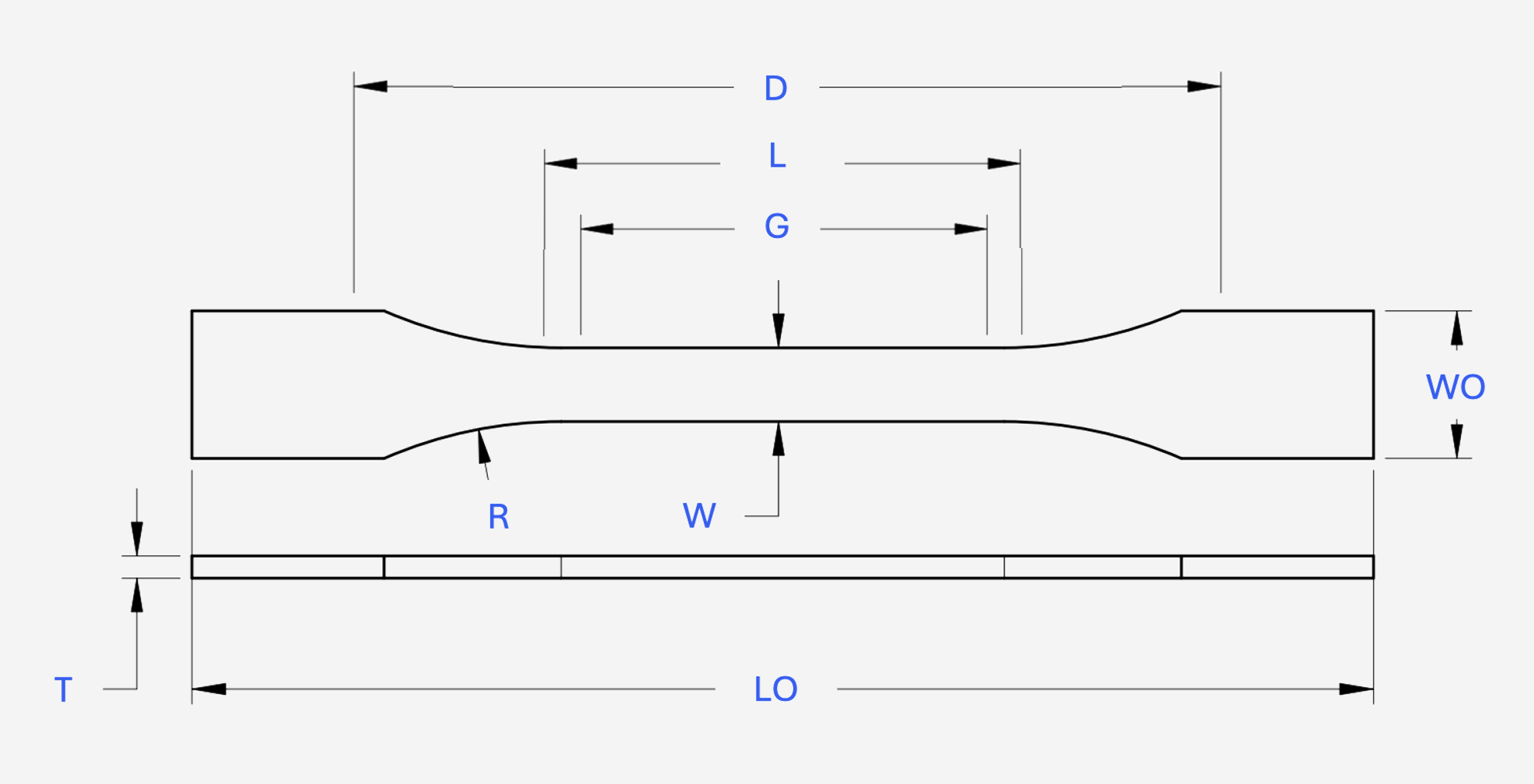
| # | Dimensions | ISO 527-1 |
|---|---|---|
| W | Width of narrow section | 3 |
| L | Length of Narrow Section | 25 |
| WO | Width overall (minimum) | 16 |
| LO | Length overall (minimum) | 80 |
| R | Radius | 6 |
| G | Gauge Length | 20 |
| D | Distance between grips | 64 |
| T | Thickness | 3 |
Specimen testing and conditioning were conducted at room temperature, defined as 23°C ± 5°C (73.4°F ± 9°F).
Apparatus
All testing was conducted using a universal testing machine equipped with suitable grips and calibrated force measurement systems in accordance with ISO 7500-1 and ASTM E4. The grips were designed to prevent slippage without introducing additional stress to the specimen, ensuring accurate load application.
An extensometer was used to measure the strain and was configured in accordance with ISO 9513 or ASTM E83 standards, depending on the test method used.
Procedure
By default five specimens of each standard are tested with the following test procedure steps:
- Specimen Measurement & Marking: The specimen dimensions across the reduced section were measured using calibrated micrometers and the gauge section length was marked.
- Specimen Mounting: The specimen was mounted in the grips, ensuring no misalignment and the machine was zeroed.
- Applying Load: The default test mode was applying force based on stress rate control with stress rates between 35-50 MPa/s in order to better attain the maximum tensile force prior to fracture.
- Data Collection: Record the load-extension or stress-strain data throughout the test.
Test Outcomes
The following mechanical properties are calculated from the tensile test data:
- Tensile Strength: The maximum stress the specimen can withstand before breaking.
- Yield Strength: Ceramics display broadly inelastic behaviour and experience brittle fracture, therefore the yield strength and tensile strength are often closely aligned.
- Elongation: Measured as the increase in gauge length after fracture, expressed as a percentage of the original gauge length.
- Modulus: Measured as the ratio of stress to strain below the proportional limit calculated as the slope of the least squares regression fit of the linear portion of the engineering stress/strain curve.
For the listed material properties in the Manta Materials data tables, the upper and lower bounds are calculated from the test specimens from both standards as well as an additional margin to account for test tolerances and uncertainty.
Flexural Testing of Advanced and Technical Ceramics
We have outlined our general procedure for flexural testing of advanced ceramics. This structured approach ensures reliable and consistent data for material characterization and quality control purposes in accordance with ISO 14704 and ASTM C1161 standards.
While we have provided a summary of our process here, it is essential to refer to the full standards for detailed guidance on preparing test specimens, conducting tensile tests, and interpreting the results.
Both standards aim to determine similar properties but differ in aspects such as specimen dimensions, testing speeds, and the calculation of flexural properties. Our materials database incorporates both approaches to provide comprehensive data representation.
Specimen Preparation
All test specimens were prepared using precise machining or molding techniques to ensure smooth surfaces free from defects such as notches, voids, or surface roughness that could affect the tensile properties.
Unless otherwise specified, all test specimens were machined with a rectangular cross section and a 45° / 0.12mm chamfer on the sharp corners. Specimens conformed to the dimensions show below:
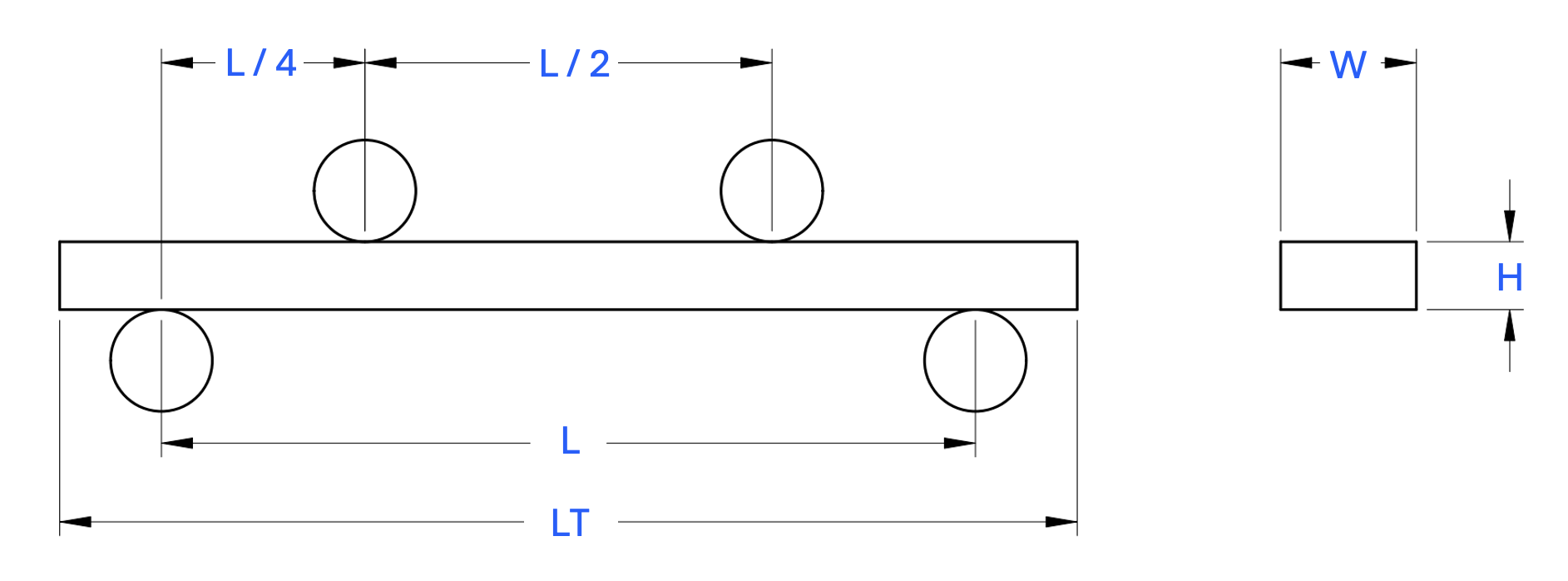
| # | Dimensions | ISO 14704 | ASTM C1161 Configuration B |
|---|---|---|---|
| L | Support Span Length | 40 | 40 |
| LT | Test Specimen Length | ≥45 | 45 |
| W | Test Specimen Width | 4±0.2 | 3±0.13 |
| H | Test Specimen Height | 3±0.2 | 4±0.13 |
Specimen testing and conditioning were conducted at room temperature, defined as 23°C ± 5°C (73.4°F ± 9°F).
Apparatus
All testing was conducted using a universal testing machine equipped with a semi-articulating 1/4-point four-point bending fixture (unless a three-point bending test was specified) and hardened steel cylindrical bearings. The width of the bearings was over three times the width of all specimens and the bearing diameter was 1.5 times the specimen height.
The force measurement systems were configured in accordance with ISO 7500-1 and ASTM E4.
Procedure
The following test procedure was used for flexural testing of ceramics according to each standard:
- Specimen Mounting: The specimen was placed in the flex fixture, ensuring that it was centered below the axis of the applied load and that there was an equal amount of overhang beyond the outer bearings.
- Applying Load: Loading was applied midway between the support bearings, at a uniform rate of direct loading until failure.
- Data Collection: The force and displacement was recorded continuously to capture the flexural behavior of the material.
Test Outcomes
The following mechanical properties are calculated from the flexural test data for ceramics:
- Flexural Strength: A measure of the ultimate strength of a specified beam in bending
- Flexural Modulus: Calculated as the ratio of stress to strain, or flexural deformation, indicating the material's stiffness or resistance to bending.
For the listed material properties in the Manta Materials data tables, the values are averaged from multiple test specimens per standard, with adjustments made for testing tolerances and uncertainties.
Vickers Hardness Testing of Advanced and Technical Ceramics
We have outlined our general procedure for Vickers hardness testing of ceramics at room temperature. This structured approach ensures reliable and consistent data for material characterization and quality control purposes in accordance with ISO 14705 and ASTM C1327 standards.
While we have provided a summary of our process here, it is essential to refer to the full standards for detailed guidance on preparing test specimens, conducting hardness tests, and interpreting the results.
Both standards aim to determine the Vickers hardness of ceramics but differ in aspects such as loads applied, and testing procedures. Our materials database incorporates both approaches to provide comprehensive data representation.
Specimen Preparation
All test specimens were prepared using precise machining techniques to ensure flat, ground and polished surfaces that are free from defects such as notches, scratches, or indentations that could affect the hardness measurements.
- ISO 14705: Specifies the use of polished specimens to a rms of <0.1μm and a minimum thickness of 0.5 mm to ensure accurate hardness measurement without influence from the substrate. Specimens were typically cylindrical.
- ASTM C1327: Specifies test pieces of at least 0.5 mm thickness, with dimensions of at least 1.5 times the diagonal of the indentation and at least 2 times the crack length whichever is greater.
Specimen testing and conditioning were conducted at room temperature, defined as 23°C ± 5°C (73.4°F ± 9°F).
Apparatus
All testing was conducted using a Vickers hardness tester Testing machine, capable of applying a predetermined test force in the range of 4,903 N (0,5 kgf) to 98,07 N (10 kgf), in accordance with ordance with ISO 6507-2. The machine was also equipped with a digital measuring microscope able to accurately determine the length of the diagonals.
For both ASTM and ISO standard tests, the indentor was a Vickers diamond pyramid type within the range 136° ± 0,5°.
Procedure
The following test procedure was used for hardness testing of ceramics according to each standard:
- Specimen Placement: The specimen was placed on the stage of the hardness tester. The surface to be tested was positioned directly under the indenter to ensure proper alignment and contact.
- Applying Load: A load was applied through the indenter onto the specimen surface for a specified dwell time. The depth or size of the indentation left by the indenter was measured to calculate hardness.
- Data Collection: The hardness number (Vickers Hardness, HV, or Knoop Hardness, HK) was calculated based on the dimensions of the indentation. Multiple readings were taken at different points on the specimen to ensure consistency and repeatability of results.
Test Outcomes
The following properties are determined from the hardness test data for ceramics:
- Hardness Number (HV or HK): The resistance of the ceramic material to indentation, calculated based on the size of the indentation left by the indenter under a specific load.
- Consistency Across Multiple Indentations: The uniformity of hardness measurements across different points on the specimen surface provides insight into the material's homogeneity and surface condition.
For the listed material properties in the Manta Materials data tables, the values are averaged from multiple test specimens per standard, with adjustments made for testing tolerances and uncertainties.
Electrical Conductivity Testing of Advanced and Technical Ceramics
We have outlined our general procedure for electrical conductivity testing of ceramics at room temperature. This structured approach ensures reliable and consistent data for material characterization and quality control purposes in accordance with ISO 29117 and ASTM D257 standards.
While we have provided a summary of our process here, it is essential to refer to the full standards for detailed guidance on preparing test specimens, conducting electrical conductivity tests, and interpreting the results.
Both standards aim to determine the electrical conductivity of ceramics but differ in aspects such as specimen dimensions, test methods, and calculation of electrical properties. Our materials database incorporates both approaches to provide comprehensive data representation.
Specimen Preparation
All test specimens were prepared using precise machining techniques to ensure they meet the required dimensions and surface conditions. Specimens were made flat, smooth, and free from defects such as voids or surface irregularities that could affect the electrical conductivity measurements.
- ISO 29117: Specifies using flat specimens with a minimum thickness of 1 mm and a sufficient size to ensure proper contact with electrodes. The surface should be smooth to ensure uniform electrical contact.
- ASTM D257: Recommends using flat, rectangular specimens with a minimum thickness of 1 mm and dimensions large enough to accommodate the electrodes. The surface must be free of contaminants and polished to ensure good electrical contact.

| # | Specimen Requirements | ISO 29117 | ASTM D257 |
|---|---|---|---|
| 1 | Minimum Thickness | 1 mm | 1 mm |
| 2 | Specimen Size | Sufficient to ensure proper electrode contact | Large enough to accommodate electrodes |
| 3 | Surface Condition | Smooth and free from defects | Polished and free of contaminants |
Specimen testing and conditioning were conducted at room temperature, defined as 23°C ± 5°C (73.4°F ± 9°F).
Apparatus
All testing was conducted using a resistivity meter or electrometer capable of measuring low conductivity materials, equipped with electrodes suitable for ceramics. The testing apparatus was calibrated in accordance with ISO 29117 and ASTM D257 standards to ensure accurate measurements of electrical conductivity.
The apparatus was equipped with a high-impedance voltage source and sensitive current measuring device to detect small currents passing through the specimen, ensuring precise determination of electrical conductivity.
Procedure
The following test procedure was used for electrical conductivity testing of ceramics according to each standard:
- Specimen Preparation: Each specimen was prepared to meet the specified dimensions and surface condition requirements. Specimens were cut or machined to provide a flat testing surface free of any surface imperfections or contaminants.
- Conditioning: The specimens were conditioned at 23°C ± 5°C (73.4°F ± 9°F) and 50% relative humidity for at least 16 hours to reach equilibrium with the testing environment, as recommended by both standards.
- Specimen Placement: The specimen was placed between the electrodes of the resistivity meter, ensuring proper alignment and contact to avoid any gaps that could affect the measurements.
- Applying Voltage: A specified voltage was applied across the specimen while the current passing through it was measured. The voltage and current were monitored to ensure they remained within the limits specified by the standards.
- Data Collection: The electrical conductivity (σ) was calculated based on the measured current, applied voltage, and specimen dimensions. Multiple measurements were taken to ensure consistency and repeatability of results.
Test Outcomes
The following electrical properties are determined from the electrical conductivity test data for ceramics:
- Electrical Conductivity (σ): The ability of a ceramic material to conduct electric current, calculated based on the measured current, applied voltage, and specimen dimensions. It is expressed in siemens per meter (S/m).
- Volume Resistivity (ρ): The measure of a material's resistance to electric current flow through its volume, inversely related to electrical conductivity. It is expressed in ohm-meters (Ω·m).
For the listed material properties in the Manta Materials data tables, the values are averaged from multiple test specimens per standard, with adjustments made for testing tolerances and uncertainties.
Chemical Durability Testing of Advanced and Technical Ceramics
We have outlined our general procedure for chemical durability testing of ceramics at room temperature. This structured approach ensures reliable and consistent data for material characterization and quality control purposes in accordance with ISO 10545-13 and ASTM C650 standards.
While we have provided a summary of our process here, it is essential to refer to the full standards for detailed guidance on preparing test specimens, conducting chemical durability tests, and interpreting the results.
Both standards aim to determine the chemical resistance of ceramics but differ in aspects such as specimen dimensions, test methods, exposure conditions, and evaluation of chemical effects. Our materials database incorporates both approaches to provide comprehensive data representation.
Specimen Preparation
All test specimens were prepared using precise machining techniques to ensure they meet the required dimensions and surface conditions. Specimens were made flat, smooth, and free from defects such as notches or surface irregularities that could affect the chemical durability measurements.
- ISO 10545-13: Specifies using flat specimens with a minimum thickness of 1 mm and dimensions large enough to allow immersion in the test solution. The surface should be smooth and free from visible flaws to ensure uniform chemical exposure.
- ASTM C650: Recommends using flat or curved specimens with a thickness of at least 1 mm. The specimen size should be appropriate for the chemical exposure method, with surfaces that are free from defects or surface contamination.

| # | Specimen Requirements | ISO 10545-13 | ASTM C650 |
|---|---|---|---|
| 1 | Minimum Thickness | 1 mm | 1 mm |
| 2 | Specimen Size | Sufficient for immersion | Appropriate for exposure method |
| 3 | Surface Condition | Smooth and free from visible flaws | Free from defects or contamination |
Specimen testing and conditioning were conducted at room temperature, defined as 23°C ± 5°C (73.4°F ± 9°F).
Apparatus
All testing was conducted using chemical resistance baths, containers, or exposure chambers equipped to maintain consistent environmental conditions and chemical concentration levels. The testing apparatus was calibrated in accordance with ISO 10545-13 and ASTM C650 standards to ensure accurate exposure and testing conditions.
The apparatus included temperature-controlled baths or containers, as well as lids or covers to minimize evaporation or contamination of the chemical solutions. The equipment was capable of holding the specimens in a manner that prevents contact with the container walls to ensure uniform chemical exposure.
Procedure
The following test procedure was used for chemical durability testing of ceramics according to each standard:
- Specimen Preparation: Each specimen was prepared to meet the specified dimensions and surface condition requirements. Specimens were cleaned and dried to remove any contaminants that could affect chemical interaction.
- Conditioning: The specimens were conditioned at 23°C ± 5°C (73.4°F ± 9°F) and 50% relative humidity for at least 16 hours to ensure uniform test conditions, as recommended by both standards.
- Exposure to Chemicals: Specimens were immersed in or exposed to the chemical test solution in a controlled environment. The exposure time, temperature, and chemical concentration were set according to the specific requirements of the test being conducted.
- Observation and Measurement: At specified intervals, specimens were removed from the chemical solution, rinsed, dried, and weighed or measured for changes in mass, dimensions, or appearance. Some tests required mechanical testing of the specimens post-exposure to determine changes in properties.
- Data Collection: Data on changes in mass, dimensions, surface condition, and mechanical properties (if applicable) were collected and recorded. Multiple measurements were taken to ensure consistency and repeatability of results.
Test Outcomes
The following properties are determined from the chemical durability test data for ceramics:
- Mass Change: The percentage change in specimen mass after chemical exposure, indicating material degradation or absorption. It is calculated by comparing the specimen's mass before and after exposure.
- Dimensional Stability: The change in specimen dimensions (length, width, thickness) after chemical exposure, used to assess the material's stability and resistance to swelling or shrinkage.
- Surface Condition: The visual or microscopic evaluation of the specimen surface for signs of chemical attack, such as cracking, crazing, discoloration, or pitting.
- Retention of Mechanical Properties: The assessment of changes in mechanical properties (e.g., tensile strength, elongation) after chemical exposure, providing insights into the material's structural integrity.
For the listed material properties in the Manta Materials data tables, the values are averaged from multiple test specimens per standard, with adjustments made for testing tolerances and uncertainties.